


Why Current Loops Outperform Voltage Signaling
In complex manufacturing facilities, sensor signals frequently travel hundreds of meters between field process vessels and central programmable logic controller (PLC) cabinets. While voltage signals (such as 0-10V) suffer significant signal attenuation due to wire electrical resistance over distance, current in a closed series loop remains identical at every single point in the circuit.
The Genius of the 4mA ‘Live Zero’
Why does the signal scale start at 4mA instead of 0mA?
- Fault Detection: If a field cable is severed, corroded, or disconnected, current immediately drops to 0.0mA. The PLC instantly recognizes this as an open-circuit fault rather than a genuine 0% process reading.
- 2-Wire Loop Powering: The baseline 4mA of continuous current provides sufficient electrical energy to power the transmitter’s internal microprocessors, ADC converters, and digital displays over the exact same two wires that carry the measurement signal.
NAMUR NE43 Standardized Diagnostic States
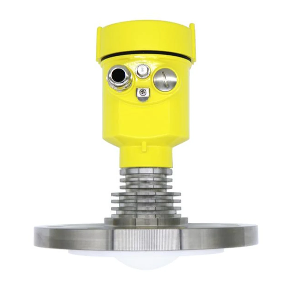
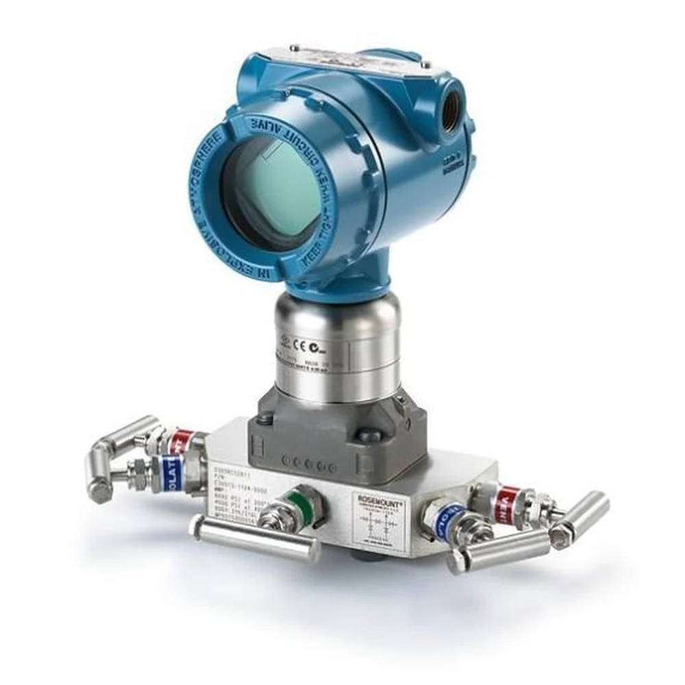
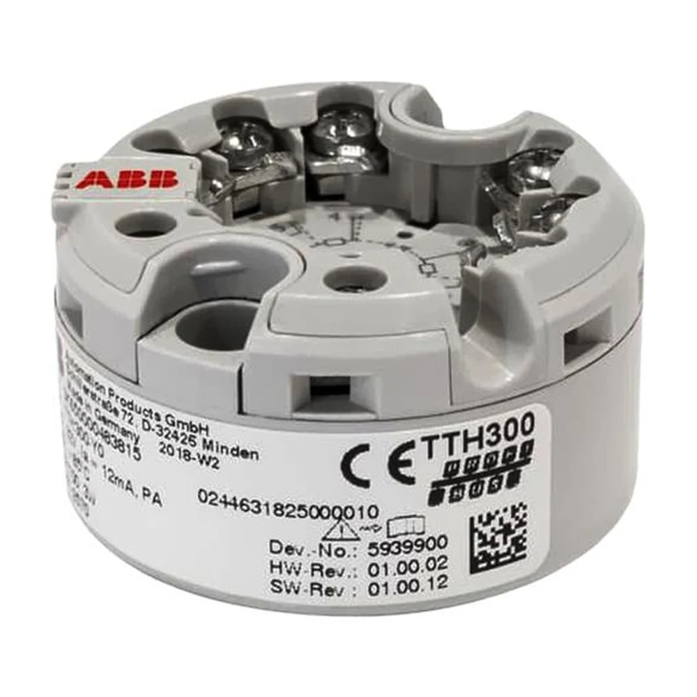
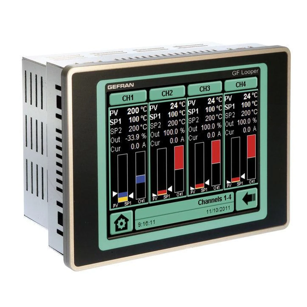
Modern industrial instruments (such as the Sky IA PT-200 and TT-300 series) adhere to the international NAMUR NE43 recommendation to communicate device health states clearly to control systems:
| Signal Range | Diagnostic Meaning |
|---|---|
| < 3.6 mA | Severe Sensor Burnout / Hardware Failure (Low) |
| 3.8 mA to 4.0 mA | Under-range (Process slightly below calibrated lower limit) |
| 4.0 mA to 20.0 mA | Normal Calibrated Operating Range (0% to 100%) |
| 20.0 mA to 20.5 mA | Over-range (Process slightly above calibrated upper limit) |
| > 21.0 mA | Severe Sensor Burnout / Hardware Failure (High) |